Structure and working principle
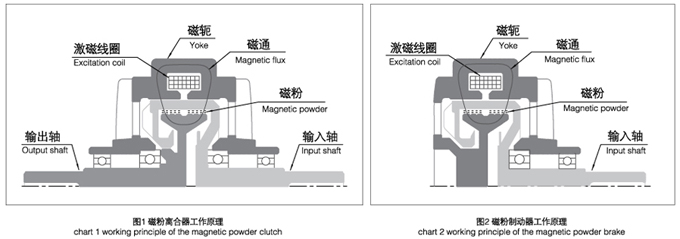
The magnetic powder clutch is composed of active rotor(input shaft),driven rotor(output shaft) and Yoke wit execitation coil. The three parts are assembled relative concentric and form a system which can rotate relatively. The annular gap between active rotor and driven rotor is full of alloy powder which has high magnetic conductivity.
The magnetic powder will bein the states of loose when the current do not pass the excitation coil.The magnetic powder will be thrown on the inner wall of active rotor. In this case ,there will not exist the interaction force between the active and driven rotor. So the magnetic powder clutch is in the state of separation , no torque transmission extis.
The magnetic powder in the working chamber will link in a link state under the action of the magnetic flux generated from the Yoke when the current pass the excitation coil. The magnetic powder clutch can transfer torque relying on the shear force generated from magnetic chain and the friction generated from the magnetic powder and working face. In this case the magnetic powder clutch is in the state of combination.
When the current is cut off,the magnetic flux will disappear with the disappearance of the magnetizing current ,the magnetic powder will be in the state of loose under the action of gravity again,and will be thrown on the inner wall of active rotor under the action of the centrifugal force. In this case ,the magnetic powder clutch will be in the state of separation again.
The magnetci powder clutch and brake have the same principle,the magnetic powder brake will form as long as the driven rotor of the magnetic powder clutch is fixed。
Featyres
The magnetizing current has a linear relationship with torque
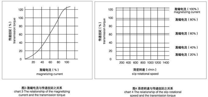
As is shown in chart 3,the transmission torque has a linear relationship with the magnetizing current, The size of the torque can get controlled within larger range.Under normal circumstance,the magnetizing current has a linear relationship with transitive torque within range of 5%-100% rated torque.
Stable slip torque
The slip rotational speed between driven rotor and active rotor do not affect the transitive torque when the magnetizing current retain unchanged, as shown in chart 4 ,That is to say,the static friction torque and the dynamic friction torque have no difference. Therefore, the torque can retain constant stably.The features are applied to tension control,users can control the tension of the roll material effectively as long as adjust the magnetizing current accurately.
Prevention heat phenomenon from slip
The friction part will generate heat inevitably or even destroyed when it keep continuous sliding .But this device has a complete cooling set ,it will not generate a lot of heat after long time running and it has a long service life.
Application:
Due to the features of the magnetic powder clutch and brake, they have been widely used in paper making,printing,plastic items,rubber industy,textile industry printing and dyeing,wire and cable,metallurgy industry and tension control of winding and unwinding in roll material processing industry.A complete set of schematic of tension control system is as follows.
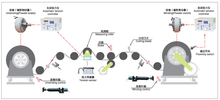
Moreover, the magnetic powder clutch can be also used in buffering start,overload protection,speed adjustment; the magnetic powder brake can also be used in test loading and braking of the transmission machinery.
Design reference
First ,let us learn the maeaning of the following words:
1.Slip rotational speed:the speed difference between input shaft and output shaft is magnetic powder chutch,the rotational speed of output shaft for magnetic powder brake;
2.Slip power:the power generated from the slip rotational speed when the magnetic powder cluch or brake transfer torque。
The selection of the magnetic powder clutch or brake rely on the maximum required torque and rotational speed. Because the temperature of all parts will rise when the slip power is converted into heat , it is guaranteed that the actual slip power is less than the rated value.: P=2∏/60×M×n
in this formula:P-slip power(unit:w)
M-working torque(unit:N•m)
n-slip rotational speed(unit:r/min)
F-working tension(unit:N)
V-line speed(unit:m/s)
Example:FZ100/Y double water cooling magnetic powder brake,the slip power is 7000W,the rate torque is 100N?m,the allowed rotational speed 1500r/min.
When it works at the rated torque,the allowed highest rotational speed is:n=(60×P)/(2∏×M)=9.55×p/M=9.55×7000/100=668.8(r/min)
When it works at the highest slip rotational speed , the allowed highest torque is:M=(60×P)/(2∏×n)=9.55×p/n=9.55×7000/100=44.6(N•m)
Notes:
Don't overload,meanwhile cool to appropriate temperature
The value of the torque/rotational speedd/slip power should be less than the rated value.The cooling mode(natural cooling/forced air cooling / water coling)
Concerning the service life
The life of the magnetic powder clutch and brake rely on the life of the magnetic powder.Generally speaking,its service life is 4500-7500 hours in the state non overloaded;But its service life can extend times in some cases,such as:the working torque of the magnetic powder clutch/brake,relative slip rotational speed and slip power can be reduced to 50%-70% of the rated value.That is to say, the margin can be enlarged as soon as possible when designing.
Concerning the torque
After the magnetic powder clutch and brake working ,the magnetic powder will be in grinding at the beginning which leat to the torque decreasing slightly , but the gap can be compensated throuhg adjustment the current。
Installation example
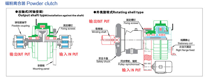
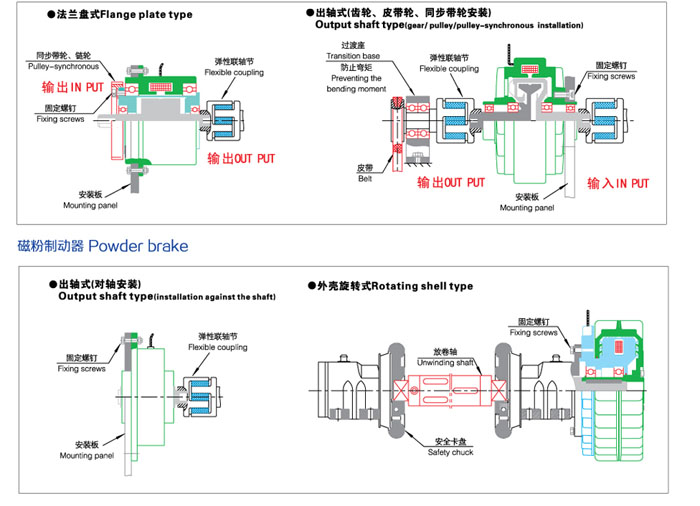
| 


